|
TRACE User Guide
TRACE Version 9.6.1
|
|
TRACE User Guide
TRACE Version 9.6.1
|
Many attributes of panels (i.e. boundaries) in TRACE can be set or changed with the command
This page describes the sub-options of this command.
Exactly one of the following options has to be specified.
Specify panel where the option is to be applied.
Specify panel family where the option is to be applied.
Options that are recognized every time the command is called
Settings for solid walls
Change solid type of selected panels.
| type | Choose from BCSymmetryPlane, BCWallInviscid, BCWallViscous |
Set Stokes boundary conditions at a solid panel.
| Type | Argument | Description |
|---|---|---|
WallFunctions | - | Spalding wall function |
WallFunctionsWernerWengle | - | Werner/Wengle wall function for LES |
WallFunctionsPressureGradient | - | Wall function with pressure gradient |
LowReynolds | - | Low Reynolds |
heatflux | \(\dot q \, [\text W / \text m^2]\) | Low Reynolds with constant heat flux \(\dot q\) |
isothermal | \(T \, [\text K]\) | Low Reynolds with constant temperature \(T\) |
WallFunctionsIsothermal | \(T \, [\text K]\) | Wall function (Spalding) with constant temperature \(T\) |
WallFunctionsHeatflux | \(\dot q \, [\text W / \text m^2]\) | Wall function (Spalding) with constant heatflux \(\dot q\) |
WallFunctionsWernerWIsothermal | \(T \, [\text K]\) | Wall function (Werner-Wengle) with constant temperature \(T\) |
WallFunctionsWernerWHeatflux | \(\dot q \, [\text W / \text m^2]\) | Wall function (Werner-Wengle) with constant heatflux \(\dot q\) |
rough | \(k_s \, [\text m]\) | Set sandgrain roughness \(k_s\) |
Set rotational velocity of a solid wall panel in revolutions per minute.
| rpm | rotational velocity |
Settings for panels or families of type entry, exit, or interface.
Sets the boundary condition on the specified panel according to the gust data corresponding to a characteristic wave (e.g. circumferential, acoustic or entropy wave).
Sets the boundary condition on the specified panel according to the gust data corresponding to a characteristic wave (e.g. circumferential, acoustic or entropy wave). Values are prescribed in relation to the steady flow solution (0.01 corresponds to a perturbation of 1% of the value provided by the steady flow solution).
Set turbulent length scale at entry.
| tls | turbulent length scale in m |
Deactivate modification of Riemann boundary values for matching of averaged and specified values
Activate modification of Riemann boundary values for matching of averaged and specified values
Set flow direction in cylindrical coordinates
| dirX | axial component of flow direction |
| dirR | radial component of flow direction |
| dirTheta | circumferential component of flow direction |
Set flow direction in cylindrical coordinates
| dirX | X component of flow direction |
| dirY | Y component of flow direction |
| dirZ | Z component of flow direction |
Prescribe an acoustic mode.
| amplitude | amplitude in Pa |
| frequency | frequency in Hz |
| circModeOrder | circumferential mode order |
| radialModeOrder | radial mode order |
Suppress specified modes from a prescribed gust.
| Type | Description |
|---|---|
entropy/Entropy | Entropy mode |
vorticityradial/Vorticityradial | Radial vorticity mode |
vorticitycircumferential/Vorticitycircumferential | Circumferential vorticity mode |
acousticdownstream/Acousticdownstream | Downstream acoustic mode |
acousticupstream/Acousticupstream | Upstream acoustic mode |
Use second order approximation to Giles2 instead of exact decomposition.
Enable rezoning for transport variables.
Control flux rezoning.
| Type |
|---|
OFF |
Euler |
NSLaminar |
NSTurbulent |
Use instantaneous band-averages for the mixing plane at the specified panel family.
Special settings for the 3D non-reflecting boundary conditions of the linear and HB solvers.
Set the discretisation order for the computation of the radial modes used in the 3D NRBC.
| order | choose 2 or 4 |
Set the parameter for the artificial damping used in the computation of the radial modes for the 3D NRBC. The default value is 1.e-4.
Set the maximal allowed number of zero crossing (radial order) for the radial eigenmodes to filter highly oscillating radial modes for the 3D NRBC. If not specified it is computed from the minimal number of cells allowed between two zero crossing.
| order |
Enables the radial mode filter for the 3D NRBC if the GMRes solver is used.
Enable the viscous extension for the 3D NRBC. Use slip if wall functions are used at hub and tip and noslip for low-Reynolds treatment.
| Type | Description |
|---|---|
slip | for wall function |
noslip | for low-Reynolds treatment |
Offset of 3D wave splitting plane from the panel family.
| offset |
Enable output of the radial modes and eigenvalues used by the 3D NRBC. The radial eigenvectors and eigenvalues are written into files in the directory specified.
| directory | Path to output directory |
Enable output of the 3D modal decomposition of the prescribed gust.
Options which do not belong to one of the previous categories.
Write average residual of a panel or panel family to a residual file.
Change boundary treatment of panel family to implicit.
Set intermittency (value of Gamma, \(0 < \gamma \le 1\), default: \(1\)) at farfield.
| intermittency | new value for \( \gamma\) |
Enabled fix if standard clipping algorithm fails.
Set cooling source terms for panel
| massflow | cooling massflow for whole panel family |
| Temperature | Absolute Total Temperature |
| velocityX | velocity in X direction |
| velocityR | velocity in radial direction |
| velocityPhi | velocity in circumferential direction |
| dirX | Injection is currently assumed to be in the plane orthogonal to the surface, the angle is the relative angle of injection to the surface. |
| dirR | currently unused, don't delete |
| dirPhi | currently unused, don't delete |
| Tu | Turbulence intensity |
| Tls | Turbulent length scale |
Set riblet geometry parameter as boundary condition and activates Riblet-Model by Koepplin et al. (2016).
| ribletHeight | height of Riblets |
| ribletWidth | distance between Riblets |
| ribletTipRadius | radius of Riblet Tip |
| ribletToFlowOrientation | relative angle between flow and Riblets (Riblets aligned with flow: ribletToFlowOrientation = 0) |
| ribletFormFactor | form factor of Riblet grooves |
Options for settings which can only be made at immediate level, i.e. at the beginning of a simulation.
Settings for panels or families of type entry, exit, or interface.
Set exit and entry boundary treatment method for the steady solver mode.
| method | one of Steady2D|Unsteady1D|Unsteady2DTimeDomain|Unsteady2DFrequencyDomain|Riemann|Steady1DCharacteristics|Nonreflecting3D|Dirichlet |
Set exit and entry boundary treatment method for the unsteady solver mode.
| method | one of Steady2D|Unsteady1D|Unsteady2DTimeDomain|Unsteady2DFrequencyDomain|Riemann|Steady1DCharacteristics|Nonreflecting3D|Dirichlet |
For a given panel family the temporal harmonics used for the "Unsteady2DFrequencyDomain" boundary conditions can be specified as list (whitespace-separated).
Relaxations factor for 2d and 3d NRBC in the HB solver. Default NRBC_RELAX_FACTOR_DEFAULT.
| factor | Relaxations factor |
Relaxations factor for global characteristics. Currently only available for steady1Dcharacteristics NRBC. Default NRBC_RELAX_FACTOR_GLOBAL_CHAR_DEFAULT.
| factor |
Relaxations factor for the row coupling in the frequency domain solvers. Its application is restricted to the range of of bands given and the factor varies linearly from factor1 to factor2 with the band index.
| bandIndexStart | |
| bandIndexEnd | |
| factor1 | relaxation factor for first band |
| factor2 | relaxation factor for last band |
Relaxations factor for mean flow adjustment in Unsteady2DFD NRBC
| factor | relaxation factor (Default: 4) |
Lower bound for blending between flux- and area-averages at interfaces. Deviations below this value are judged to be physical, so flux-averaged values are used if the relative difference is below this value.
| factor | Default: 0.05 (i.e. 5% deviation from the area-averaged value) |
USE_FLUX_AREA_AVERAGE_BLENDING Upper bound for blending between flux- and area-averages at interfaces. Deviations above this value are judged to be unphysical and the flux averages are replaced completely with area-averages.
| factor | Default: 0.2 (i.e. 20% deviation from the area-averaged value) |
USE_FLUX_AREA_AVERAGE_BLENDING Activate blending between flux- and area-averages.
Relaxations factor for treatment of perturbations in Unsteady2DFD NRBC in pseudo time.
| factor | Default: 0.85 |
Activate Hagstrom extension of Unsteady2DTimeDomain boundary conditions.
Set the imaginary frequency shift for the 2D and 3D NRBC. Defaults to 1.e-3. Now obsolete. Use ANGULAR_FREQUENCY_IMAG_SHIFT instead.
Set the imaginary frequency shift for the 2D and 3D NRBCs. Defaults to 1.e-3.
| shift | angular frequency shift (non-dimensionalised with reference length and speed of sound) |
Use the meridional velocity as reference vector for Giles2 boundary conditions in the frequency domain solvers instead of the face normal.
Use the banded boundaries associated to the panel family for applying the boundary conditions.
Activate face-wise switch between entry and exit boundary conditions (only applies to Riemann boundary conditions) If this is used, it is recommended to provide back flow boundary conditions, e.g. a pressure field in the 2D gust entry file.
Define radial flux reconstruction and exchange method on mixing plane.
| order | one of '1stOrder', '2ndOrder' (default) |
Use numerical fluxes (including viscous components) for flux averaging. Moreover, inviscid fluxes at zonal interfaces use upwind schemes, whereas the standard flux averaging is based on central Euler fluxes.
Setup bands at specified panel family.
Activate band merging near hub and casing. Bands whose upper boundary has relative height below \(\delta\) will be merged with first one. Bands whose lower boundary is above \( 1-\delta \) will be merged with last one.
| delta | relative height of bands to be merged |
Activate use of time-dependent, two-dimensional gust data (use of a new gust data set per time-step). It read at each time-step the boundary values from files whose name is generated from the format string <baseFileName> and the current time step index. The index starts with 0 at time step <timeStepRef>. The boundary condition is then time-periodic and has a period of <nBoundaryFiles> time steps.
Enable PID mass flow controller and set its properties. The PID controller adjusts a control variable (here pressure) to bring a process variable (here mass flow) close to a preset value. The new value of the control variable is calculated based on the current error (Proportional), accumulated past errors (Integral), and possible future errors based on current rate of change (Derivative).
| massFlow | target mass flow |
| proportionalGain | non-negative weight for current error value |
| integralGain | non-negative weight for accumulated past values of the error |
| derivativeGain | non-negative weight for possible future values of the error based on current rate of change |
| verbose | 0 (false) or 1 (true) |
Set length of interval for temporal averaging of integral values on panel families in unsteady computations (default: number of time steps per period).
| nTimeSteps | number of time steps |
Set global values for dirichletInflow boundary condition.
Set the static temperature at a bleed inlet.
See Phase lag for the theory related to the phase lag boundary conditions.
Deactivate phase-lag flux and state reconstruction at zonal- and zonal-mixed interfaces.
Force phase-lag to be used in the panel family regardless of the inter-blade phase-angle (block group must be unsteady).
Set number of harmonics used for the phase-lag method in the unsteady solver.
Set the harmonics to be used by the phase-lag method in the unsteady solver.
You can activate the synthetic turbulence generator (STG) and set its options according to the following commands:
Activate a synthetic turbulence generator (STG) at the specified panel family.
Use global isotropic value for STG parameter Reynolds stress at the specified panel family.
Activate periodic fix formulated by Morsbach and Franke [37] for the synthetic turbulence generator according to Shur et al. [49] at the specified panel family. Use argument 'y' or 'yz' to apply the periodic fix in the corresponding direction(s) (case insensitive).
Write spectrum of the turbulence generator with initialized flow variables.
The factor \(\frac{2\pi}{k^nl_{e,\max}}\) in the \(x\)-component of the pseudo-position vector of Shur et al. is replaced with 1.
Improve the dependence on the relative inflow angle by evaluating the y coordinate to a frame of reference where the relative y velocity is 0.
Set the bulk state in the absolute frame of reference used by STG Shur et al. [49]. Velocity is used for temporal evolution, density and pressure to compute viscosity for Kolmogorov scale.
Using the HB-method with zonal interfaces offers great flexibility in mesh generation and a way of connecting secondary flow paths. There are some adjustments to tune your setup:
For a given panel family of the type ZONAL/ZONAL_MIXED the spatial modes allowed in any mode set (collection of transformed modes for a harmonic set) can be specified as list of circumferential wave numbers (whitespace-separated). This narrows the mode sets used by the re-zoning algorithm to the specified circumferential wavenumbers and can be used to avoid clocking or reduce numerical costs.
For a given panel family of the type ZONAL/ZONAL_MIXED the highest frequency allowed in any mode set (collection of transformed modes for a harmonic set). The respective mode sets are cut above the specified frequency. The re-zoning costs can be reduced by specifying e.g. the highest frequency resolved on the neighbour's side.
Two variants to impose the boundary states are available for the DG solver: the boundary state can be either directly imposed via the advective flux function of the boundary state or via the numerical flux function of the boundary state and inner state. Using this command, the default can be overwritten and the numerical flux function can be manually turned on or off for each panel family.
The defaults are set to:
1) Advective flux function of the boundary state in case of
2) Numerical flux function of the boundary state and the inner state in case of
The boundary face state can either be linear interpolated from inner and ghost cell or directly set by the bdPhysFct. This leads currently to a different face state in the corrector step (due to updated inner cell values after the predictor step).
Curently, INTERPOLATE_BC_FACE_STATE is set to On by default. Only for combustion, INTERPOLATE_BC_FACE_STATE is Off by default
The treatment can can be manually turned on or off for each panel family.
Apply Farfield boundary conditions for HB in the time domain instead off the frequency domain.
Use the incompressible formulation of the Farfield boundary conditions. This should not be used for Mach numbers greater than 0.3.
Deactivate flux reconstruction at zonal- and zonal-mixed interfaces.
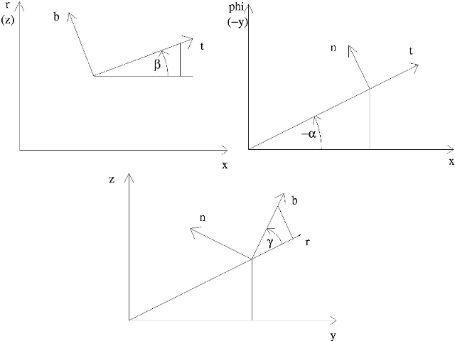
This section describes how to use the vortex generator model (Panel based vortex generator) implemented in TRACE. Control of the vortex generator model is carried out using the control file, in practice, the vortex generator model is treated as an additional attribute of a solid boundary and activated using the Change Panel Attribute Command command. Some hints concerning the handling of the model are given below.
The normal vector in the span-wise direction of the vortex generator is calculated from the user-specified angles \(\alpha\), \(\beta\), and \(\gamma\) shown in the following figure. The upper two figures that show \(\alpha\) and \(\beta\) refer to cylindrical geometry and the axial-circumferential-radial coordinate system. For plane geometry the Cartesian coordinate axis designations are given in brackets.
| location | Location of the vortex generator on the panel. The implementation of the vortex generator model is only valid for certain geometrical situations, e.g. at the hub or the casing of a rotational machine or on the blades. Values are: casing or blade. |
| iStart | Start of index range in i |
| iEnd | End of index range in i |
| jStart | Start of index range in j |
| jEnd | End of index range in j |
| kStart | Start of index range in k |
| kEnd | End of index range in k |
| nLayers | Number of layers for the source term model normal to the wall. Typical values: 1-5 |
| alpha | Angle \(\alpha\) [degrees] of the spatial orientation of the vortex generator. |
| beta | Angle \(\beta\) [degrees] of the spatial orientation of the vortex generator. |
| gamma | Angle \(\gamma\) [degrees] of the spatial orientation of the vortex generator. |
| tag | Tag for postprocessing. |
 1.9.1
1.9.1